ButtonBox
About
Design
Construction
|
 |
|
| |
|
ButtonBox Construction
I kind of made this project up as I went along, with the circuits starting life on a breadboard. Once I had it working well and had adjusted the timing of the monostables, I committed it to stripboard. I still only had a vague plan for the board layout, but left enough space to be able to put all the connectors and diodes where I needed them.
The case is a simple wedge-shaped console case with enough space to comfortably fit all the switches and dials I wanted, as well as containing the USB board and my switch adaptor board. It included small standoffs for supporting PCBs, but due to the narrow front edge, they held my board too high to fit the connectors under the switches mounted on the top half. So I removed them, instead opting to drill through the case and secure the boards that way. Fortunately, the plastic of the case was thick enough that I could step drill the underside so that the screw heads didn't protrude from the bottom. Holes were provided in the USB controller PCB, and I drilled similar holes in the corner of my board to mount it in the same way.
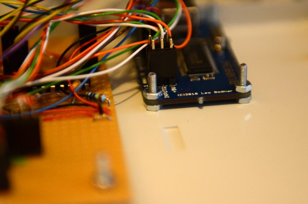 Close up of PCB mounting bolts Close up of PCB mounting boltsThe controls on the front were mounted in three rows - push buttons along the bottom, toggle switches along the middle row and rotary knobs along the top. I used DPDT toggle switches as I wanted the option of having LEDs to show the current status of the switch, though I haven't bothered with that yet. Eight of each switch type were included, and six rotary knobs due to needing a little more space between them. The rotary controls consist of four encoders with integrated push buttons and two potentiometers. All were fitted with standard 0.1-inch pin connectors to match the headers on the boards. All controls bar the potentiometers connected to my adaptor board, which itself gets its power from the USB board.
|

|
|
|
|
| |
Although I left myself what seemed like a lot of room, the sheer number of diodes connected to common circuits meant I ran out of space and had to overlap many of the diodes. It's quite messy but it works fine! Also, since I used stripboard and didn't bother having a proper PCB made, I needed to add lots of short jumper wires, which doesn't help the appearance at all. And finally, there are simply so many connections to the adaptor board that it really fills the case up with the complete mess of wires you can see here.
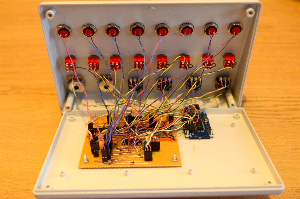 Inside the finished ButtonBox Inside the finished ButtonBoxStill, it works! Finally, after testing all the controls and fixing two mistakes (one where I neglected to cut a track and one where I miscounted holes), I had to label the controls on the front panel. I mapped the controls in both Elite: Dangerous and Microsoft Flight Simulator X, and got my trusty label maker out to print some temporary labels until I was sure I was happy with the setup. The plan was to eventually print a full-panel sheet that fits the recess in the console's face, but having used it with the temporary labels, I might just leave them as they are...
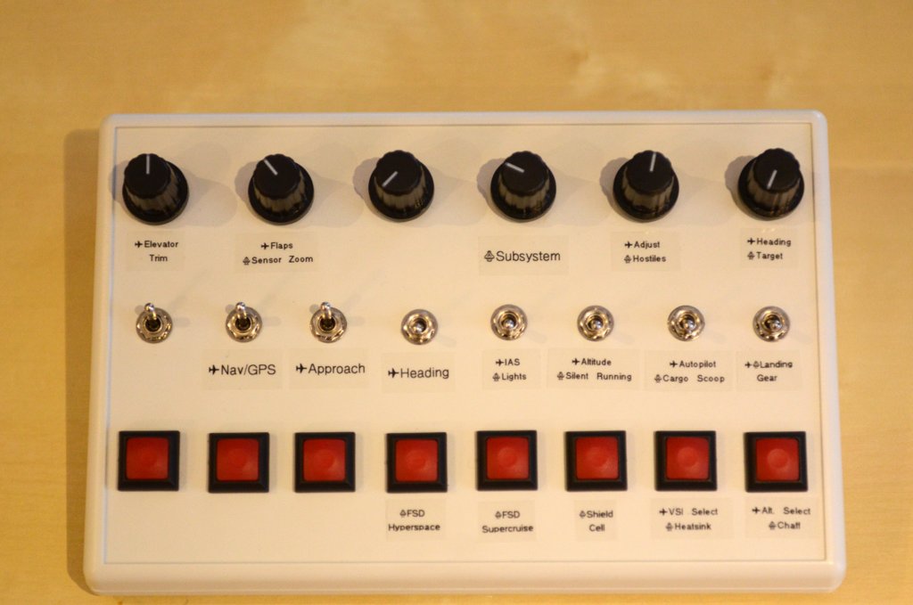 Front of the ButtonBox Front of the ButtonBoxSorry about the fuzziness from the camera shake!
|
|
|
|
|
| |
|
Parts List
Here's a list of the parts I used to build the ButtonBox:
|
|
|
|